Click on an image to go directly to a system or scroll to see the systems in this gallery.
| OdeFactory Images and Annotations |
|
|
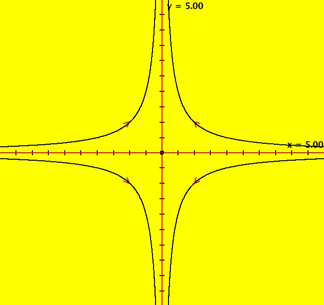
View/Sys/Gal: Ode "2D: p. 99 (-x,y+k*x^2), k = .00; " in "PerkoExs."
Range: (vMax,vMin) = (5.000,-5.000), (hMin,hMax) = (-5.000,5.000)
VFld: (-x,y+k*x^2), k = .00; This system of odes is defined by the equations: dx/dt = -x, dy/dt = y+k*x^2 Parameters are: k = .00; The problem is to find the separatrix system for k = 1. The method of using a parameter to transition from the linearized system, dx/dt=-x, dy/dt=y, where the separatrix system is easy to find, to the nonlinear system, where it is not so easy to find, will be used. An inspection of the vector field for the linearized system shows that the axes form the separatrix system. For a more rigorous approach, apply WA to the coefficient matrix of the linearized system, {{-1,0},{0,1}}, at (0,0) to find the eigenvalues and eigenvectors: λ1 = -1, v1 = (1,0), λ2 = 1, v2 = (0,1). The four red separatrix lines, in the eigen directions, are drawn by starting trajectories at (0,+-.001) and (+-.001,0). The separatrices and the fixed point partition the phase space into four open regions called components. The four black trajectories starting at (+-1,+-1) are generic trajectories in each of the four components. The R2+ view is the global phase portrait and it contains all there is to know, gualitatively, about the system. To see the separatrices for the linear system morph into the separatrices for the nonlinear system, click the "Adj Ctrl Params..." button and adjust k from 0 to 1. Also try adjusting k from 0 to -1. For a 3D variation of this problem, see the 3D p. 105 systems in this gallery.
|
|
|
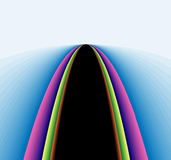
View/Sys/Gal: EMap "2D: p. 99 (-x,y+k*x^2), k = .00; EMapCT3" in "PerkoExs."
Range: (vMax,vMin) = (7.713,5.127), (hMin,hMax) = (-1.190,1.181)
VFld: (-x,y+k*x^2), k = .100; This iteration is defined by: x <- -x, y <- y+k*x^2. Parameters are: k = .100; EMap CT: 3
|
|
|
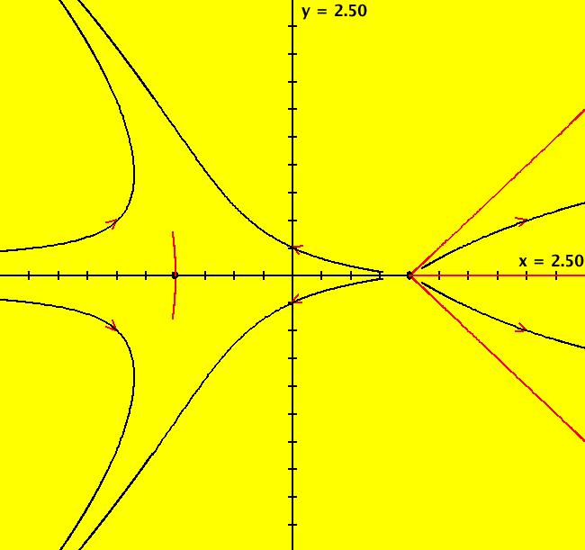
View/Sys/Gal: Ode "2D: p. 102 (-2*y,4*x*(x-1)*(x-.5))" in "PerkoExs."
Range: (vMax,vMin) = (2.500,-2.500), (hMin,hMax) = (-2.500,2.500)
VFld: (x^2-y^2-1,2*y) This system of odes is defined by the equations: dx/dt = x^2-y^2-1, dy/dt = 2*y The goal here is to find the finite and infinite fixed points and the separatrices. The two finite fixed points are (x,y) = (+-1,0). On the y axis, dy/dt = 0 so two obvious fixed points at infinity are (u,v) = (+-1,0). There are four less obvious fixed points at infinity. To find them, view the vector field and look for straight line solutions. Inspection of the vector field indicates that the lines y = +-x-1 may be solutions. You can verify that they are indeed solution curves by plugging them into the differential equations. So (u,v) = (+-1,+-1)/sqrt(2) are four additional fixed points at infinity. The x > 1 parts of the two straight lines are separatrices. The separatrices are the 7 red curves emanating from the 2 finite fixed points. The 7 separatrices, shown in red, together with the two finite fixed points, partition the global phase space into 6 components. A generic black trajectory is shown in each component. ICs of (-1,+-.00001) and (-1,0) give the first 4 separatrices. ICs of (1.001,+-.001) and (1.001,0) give the other 3 separatrices. Switch to the R2+ view to see the global phase portrait. To convince yourself that the separatrices do partition R2+ into 6 components, start additional trajectories in each component and note that the new trajectories in each component are topologically equivalent to the generic trajectory in that component. Try the EMap view with various color tables.
|
|
|
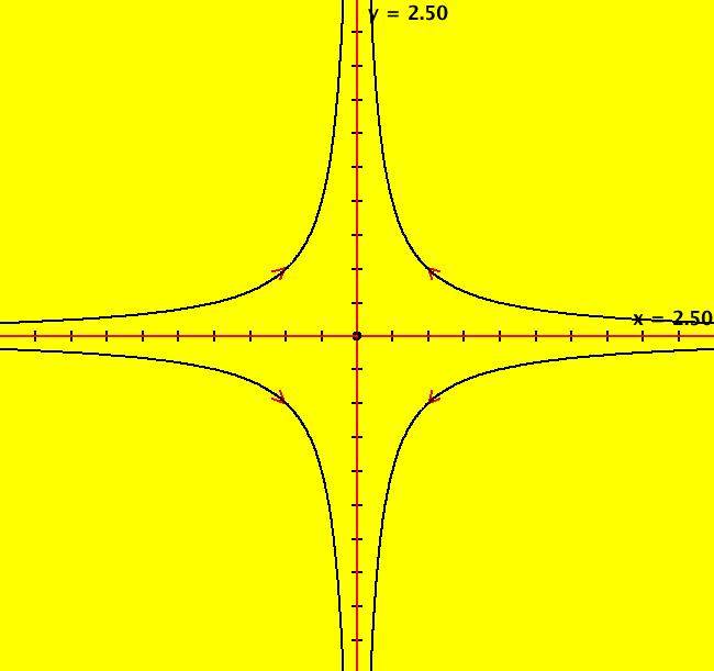
View/Sys/Gal: Ode "2D: p. 111 (-x-a*y^2,y+a*x^2), a=0" in "PerkoExs."
Range: (vMax,vMin) = (2.500,-2.500), (hMin,hMax) = (-2.500,2.500)
VFld: (-x-a*y^2,y+a*x^2), a=0 This system of odes is defined by the equations: dx/dt = -x-a*y^2, dy/dt = y+a*x^2 Parameters are: a=0 For a = 0 - fixed points are (x,y) = (0,0) and (u,v) = (+-1,0), (0,+-1) at (x,y) = (0,0), λ1 = -1, λ2 = 1 with v1 = (1,0) and v2 = (0,1) - separatrix ICs: (+-.001,0), (0,+-.001) - stable manifold = x axis - unstable manifold = y axis - other ICs: (+-.5,+-.5). Switch to the R2+ view to see the global phase portrait. While in the R2+ view, adjust parameter "a" to watch the separatrices for the system change as it becomes nonlinear.
|
|
|
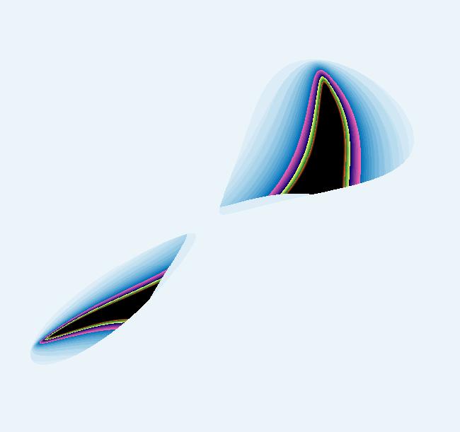
View/Sys/Gal: EMap "2D: p. 111 (-x-a*y^2,y+a*x^2), a=0 EMapCT3" in "PerkoExs."
Range: (vMax,vMin) = (13.048,-31.544), (hMin,hMax) = (-26.867,10.602)
VFld: (-x-a*y^2,y+a*x^2), a = .050; This iteration is defined by: x <- -x-a*y^2, y <- y+a*x^2. Parameters are: a = .050; EMap CT: 3
|
|
|
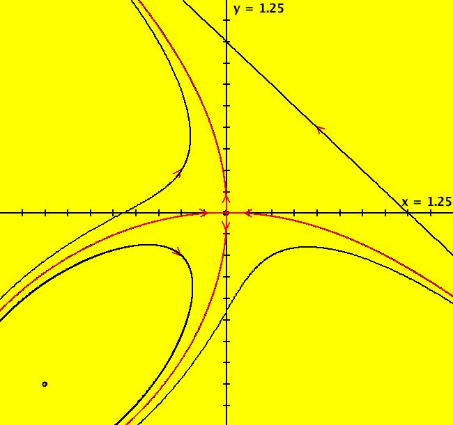
View/Sys/Gal: Ode "2D: p. 111 (-x-y^2,y+x^2)" in "PerkoExs."
Range: (vMax,vMin) = (1.250,-1.250), (hMin,hMax) = (-1.250,1.250)
VFld: (-x-y^2,y+x^2) This system of odes is defined by the equations: dx/dt = -x-y^2, dy/dt = y+x^2 In this example I will demonstrate another way to study the "a = 1" case of the previous example. The finite fixed points are at (x,y) = (0,0) and (-1,-1). Viewing the vector field, it looks like the straight line y = -x+1 is a solution (you can verify this by checking to see if dy/dt = d(-x+1)/dt when y = -x+1, which it does). Parallel lines map to the same points at infinity in R2+ (prove this or just view the system dx/dt = a, dy/dt = b in R2+ as you vary the parameters) so, noting that y = x in R2+ has points at (u,v) = (-1,1)/sqrt(2), = (1,-1)/sqrt(2) on u^2 + v^2 = 1 gives us the fixed points at infinity. In general, when P and Q are polynomials of the same degree, using the highest degree terms of P and Q and solving the system of equations u*Q2(u,v) = v*P2(x,y) on the unit circle gives the fixed points at infinity. Applying WA to u*(u^2) = v*(-v^2), u^2+v^2 = 1 also gives, (u,v) = (-1,1)/sqrt(2), = (1,-1)/sqrt(2) Approximate (local) separatrices at (0,0) can be found by solving an integral equation by successive approximations. This algorithm is demonstrated in the proof of the "Stable Manifold Theorem," Perko, p. 108. The stable manifold near (0,0) is y ~= -(x^2)/3 + O(x^5) and the unstable manifold near (0,0) is x ~= -(y^2)/3 + O(y^5). For this example, there are three ways to draw the approximate separatrix system near (0,0). (1) The hard way: we could use the equations given above to start four trajectories on the stable and unstable manifolds near (0,0) at (+-.1,-.003333) and (-.003333,+-.1) respectively. (2) An easier way: since the fixed point is a saddle loop, we could start a single trajectory in a saddle, near (0,0), outside of the loop at (-.005,0). Try this by clearing the view and starting a trajectory at (-.005,0). Zoom in to see where the trajectory actually goes. (3) The easiest way: move the cursor over (0,0) to draw the fixed point solution (a small open circle appears) then with the cursor in the circle, hold the shift key down and wiggle it a bit. This method is fast, but generally too crude. It can produce more approximate separatrices than you want. Give it a try. The first method was used to draw four black trajectories near (0,0) with arrowheads and the second method was used to draw a red trajectory on top of the black trajectories. To see the black trajectories, click on (0,0) and delete the red trajectory starting at (-.005,0). The three separatrices are the red loop and the two red half-lines. Together with the fixed point at (0,0), they partition the phase space into 3 components. Adding the 3 representative trajectories in the 3 components gives the global phase portrait. See the R2+ view. The red loop plus the fixed point is called a separatrix cycle. Note: the system is actually a Hamiltonian system where H = -x*y-x^3/3-y^3/3 and the separatrix curve is just the level curve given by -x*y-x^3/3-y^3/3 = 0. Apply WA to H.
|
|
|
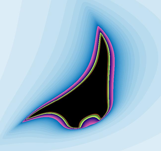
View/Sys/Gal: EMap "2D: p. 111 (-x-y^2,y+x^2) EMapCT3" in "PerkoExs."
Range: (vMax,vMin) = (0.852,-1.648), (hMin,hMax) = (-1.606,0.894)
VFld: (-x-y^2,y+x^2) This iteration is defined by: x <- -x-y^2, y <- y+x^2. EMap CT: 3
|
|
|
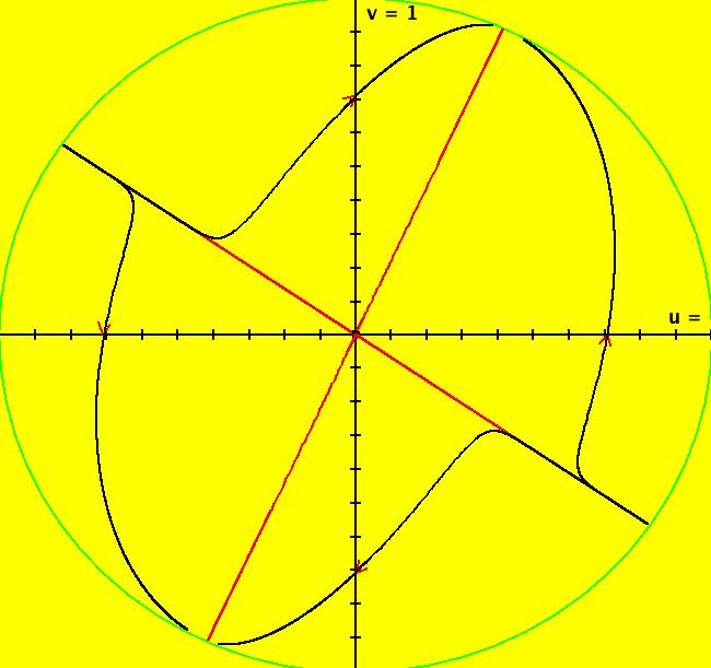
View/Sys/Gal: Ode "2D: p. 141: (x+2*y+a*(x^2-y^2),3*x+4*y-a*x*y), a=0" in "PerkoExs."
Range: (vMax,vMin) = (1.000,-1.000), (hMin,hMax) = (-1.000,1.000)
VFld: (x+2*y+a*(x^2-y^2),3*x+4*y-a*x*y), a=0 This system of odes is defined by the equations: dx/dt = x+2*y+a*(x^2-y^2), dy/dt = 3*x+4*y-a*x*y Parameters are: a=0 In the R2+ view, you can watch the four fixed points at infinity move on the unit circle as you adjust "a."
|
|
|
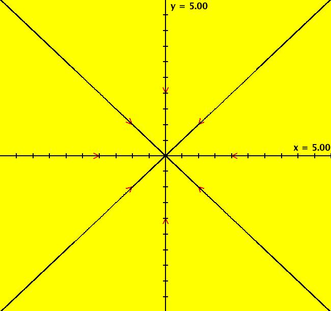
View/Sys/Gal: Ode "2D: p. 142: (-x-a*y/F,-y+a*x/F), a=0, F=ln(sqrt(x^2+y^2))" in "PerkoExs."
Range: (vMax,vMin) = (5.000,-5.000), (hMin,hMax) = (-5.000,5.000)
VFld: (-x-a*y/F,-y+a*x/F), a=0, F=ln(sqrt(x^2+y^2)) This system of odes is defined by the equations: dx/dt = -x-a*y/F, dy/dt = -y+a*x/F Parameters are: a=0 Functions are: F=ln(sqrt(x^2+y^2)) See the IMap and EMap views for a = +-0.27.
|
|
|
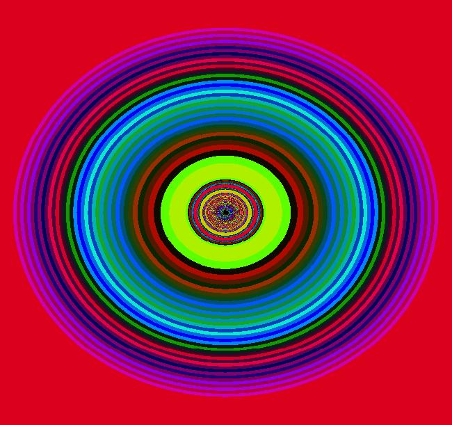
View/Sys/Gal: EMap "2D: p. 142: (-x-a*y/F,-y+a*x/F), a=0, F=ln(sqrt(x^2+y^2)) EMapCT6" in "PerkoExs."
Range: (vMax,vMin) = (7.980,-8.020), (hMin,hMax) = (-7.323,7.343)
VFld: (-x-a*y/F,-y+a*x/F), a = .350; , F=ln(sqrt(x^2+y^2)) This iteration is defined by: x <- -x-a*y/F, y <- -y+a*x/F. Parameters are: a = .350; Functions are: F=ln(sqrt(x^2+y^2)) EMap CT: 6
|
|
|
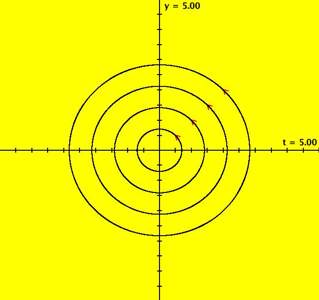
View/Sys/Gal: Ode "2D: p. 143: (-y+a*x*F*sin(1/F),x+a*y*F*sin(1/F)), a=0, F=sqrt(x^2+y^2)" in "PerkoExs."
Range: (vMax,vMin) = (5.000,-5.000), (hMin,hMax) = (-5.000,5.000)
VFld: (-y+a*x*F*sin(1/F),x+a*y*F*sin(1/F)), a=0, F=sqrt(x^2+y^2) This system of odes is defined by the equations: dx/dt = -y+a*x*F*sin(1/F), dy/dt = x+a*y*F*sin(1/F) Parameters are: a=0 Functions are: F=sqrt(x^2+y^2) Adjust "a" in the Ode view. Toggle to the IMap view then get into the 3D/(x,y) subview and adjust "a."
|
|
|
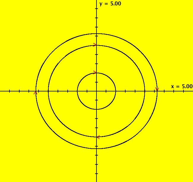
View/Sys/Gal: Ode "2D: p. 172 (y,-(x+a*(sin(x)-x))), a=0" in "PerkoExs."
Range: (vMax,vMin) = (5.000,-5.000), (hMin,hMax) = (-5.000,5.000)
VFld: (y,-(x+a*(sin(x)-x))), a=0 If a = 0 we have the linear pendulum, dx/dt = y, dy/dt = -x and if a = 1 we have the nonlinear pendulum, dx/dt = y, dy/dt = -sin(x). The a = 0 case has a single fixed point at (0,0), and circular trajectories. The a = 1 case has fixed points at (n*pi,0), n = 0, +-1, +-2, ... with eigenvalues, λ = +-i*sqrt(cos(n*pi)) = +-i, so n = even gives a center and n = odd gives a saddle. To draw the approximate saddle separatrices near (odd*pi,0), for the a=1 case, ICs of (+-pi,0). The other ICs are (0,1) and (0,+-2.5). Slide "a" from 0 to 1 to see the separatrices appear. In the IMap view, all orbits are cycles (squares) for a = 0. For a > 0 all orbits spiral to (0,0) and spiral out to infinity for a < 0. The motion is cw. Try the EMap view for a = -.5 zoomed in once.
|
|
|
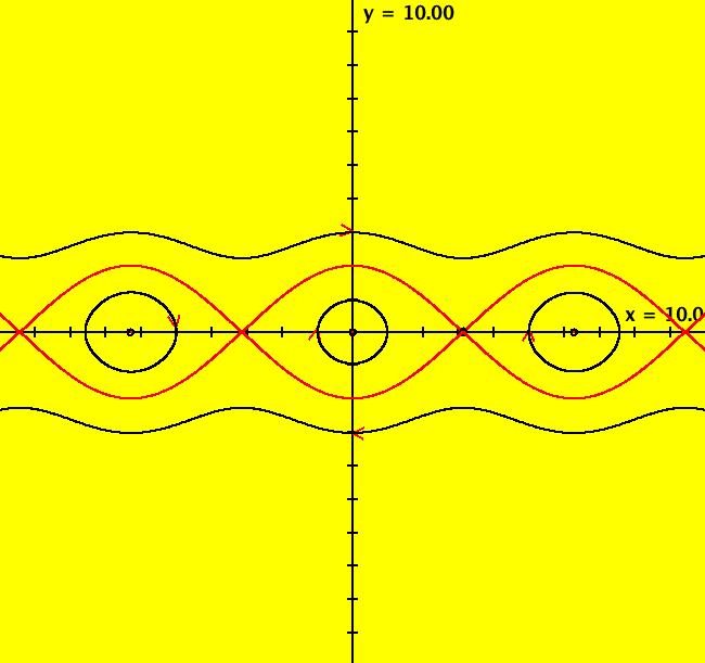
View/Sys/Gal: Ode "2D: p. 172 (y,-sin(x))" in "PerkoExs."
Range: (vMax,vMin) = (10.000,-10.000), (hMin,hMax) = (-10.000,10.000)
VFld: (y,-sin(x)) This system of odes is defined by the equations: dx/dt = y, dy/dt = -sin(x) in the (t,x,y) coordinate system. All of the separatrices can be drawn by using just two ICs (pi,+-.0001), in the saddle, just above and just below the fixed point at (pi,0). The fixed points at infinity accumulate at (u,v) = (+-1,0). The separatrices are the infinite number of top and bottom sets of red curves not including the fixed points. Each "eye" is a separatrix cycle. The phase space has an infinite number of components consisting or the two regions above and below the red curves and the infinite number of "eye" shaped regions. Generic trajectories in a few of the components are drawn in black.
|
|
|
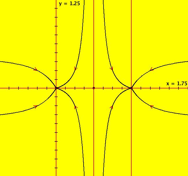
View/Sys/Gal: Ode "2D: p. 175 (-4*x*(x-1)*(x-.5),-2*y)" in "PerkoExs."
Range: (vMax,vMin) = (1.250,-1.250), (hMin,hMax) = (-0.750,1.750)
VFld: (-4*x*(x-1)*(x-.5),-2*y) Gradient and Hamiltonian Systems ~~~~~~~~~~~~~~~~~~~~~~~~~~~~~~~~ This system of odes is defined by the equations: dx/dt = -Vx = -4*x*(x-1)*(x-.5), dy/dt = -Vy = -2*y where V(x,y) = x^2*(x-1)^2+y^2. It is called a gradient system. In general, vector fields v1 = (P,Q) and v2 = (Q,-P) are orthogonal since v1 dot v2 = P*Q-Q*P = 0 where "dot" is the dot product of the two vectors. Consequently, the two systems dx/dt = P(x,y), dy/dt = Q(x,y) and dx/dt = Q(x,y), dy/dt = -P(x,y) have orthogonal trajectories. If we rename V as H and call H(x,y) = x^2*(x-1)^2+y^2 the Hamiltonian function, then the system system dx/dt = Hy = Vy, dy/dt = -Hx = -Vx is called a Hamiltonian system. The vector field for the corresponding gradient system, (-Vx,-Vy), and the vector field for the Hamiltonian system, (Hy,-Hx) = (Vy,-Vx) are orthogonal so the trajectories for the two systems are orthogonal. The 3 finite fixed points are at (x,y) = (0,0), (.5,0) and (1,0). For the system under consideration, the 4 fixed points at infinity are at (u,v) = (0,+-1) and (+-1,0). The 10 separatrices are the 6 red vertical half-lines at x = 0, .5, 1, y != 0 and the 4 red segments of the x axis separated by the 3 finite fixed points. The separatrices partition the phase space into 8 components. Switch to the R2+ view to see the global phase portrait.
|
|
|
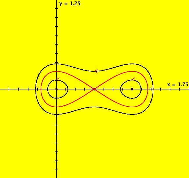
View/Sys/Gal: Ode "2D: p. 176 (-2*y,4*x*(x-1)*(x-.5))" in "PerkoExs."
Range: (vMax,vMin) = (1.250,-1.250), (hMin,hMax) = (-0.750,1.750)
VFld: (-2*y,4*x*(x-1)*(x-.5)) This system of odes is defined by the equations: dx/dt = Hy = -2*y, dy/dt = -Hx = 4*x*(x-1)*(x-.5) where H(x,y) = x^2*(x-1)^2+y^2 is called a Hamiltonian function. This is the companion system to the gradient system of the previous example. The level curves of H(x,y) are integral curves (trajectories or orbits) of the system and are given by H(x,y) = c. Fixed point ICs: centers at (0,0), (1,0) saddle at (.5,0). Fixed points at infinity: none. Other ICs are: outside trajectory: (.5,.25), separatrices: (.5,.001), inside trajectories: (0,.13), (1,.13) Separatrices: the two red loops. Separatrix cycles: the two red loop joined at the fixed point (1,0). The trajectories of this system are orthogonal to those of the previous system. The global phase portrait has 3 components.
|
|
|
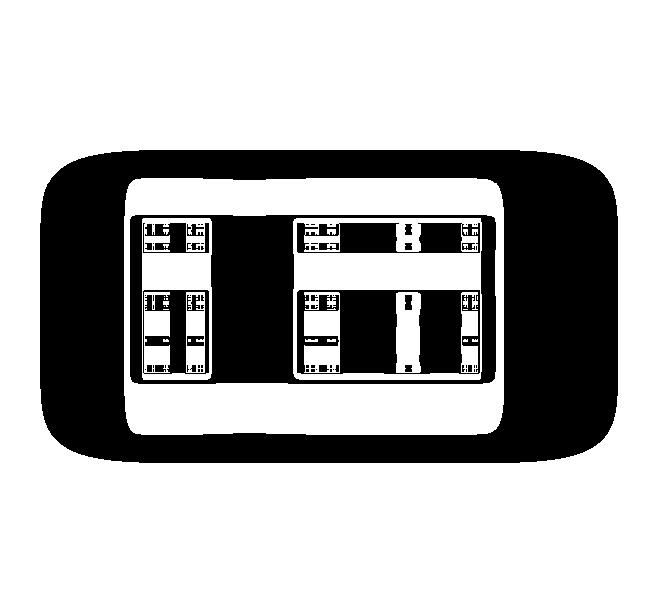
View/Sys/Gal: EMap "2D: p. 176 (-2*y,4*x*(x-1)*(x-.5)) EMapCT9" in "PerkoExs."
Range: (vMax,vMin) = (1.000,-1.500), (hMin,hMax) = (-0.690,1.660)
VFld: (-2*y,4*x*(x-1)*(x-.5)) This iteration is defined by: x <- -2*y, y <- 4*x*(x-1)*(x-.5). EMap CT: 9 What's on TV? This is a very strange fractal.
|
|
|
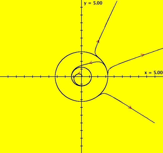
View/Sys/Gal: Ode "2D: p. 247 two limit cycles" in "PerkoExs."
Range: (vMax,vMin) = (5.000,-5.000), (hMin,hMax) = (-5.000,5.000)
VFld: (-y+x*((x^2+y^2)^2-3*(x^2+y^2)+1),x+y*((x^2+y^2)^2-3*(x^2+y^2)+1)) This system of odes is defined by the equations: dx/dt = -y+x*((x^2+y^2)^2-3*(x^2+y^2)+1), dy/dt = x+y*((x^2+y^2)^2-3*(x^2+y^2)+1). Looks like limit cycles at r = .609, 1.605.
|
|
|
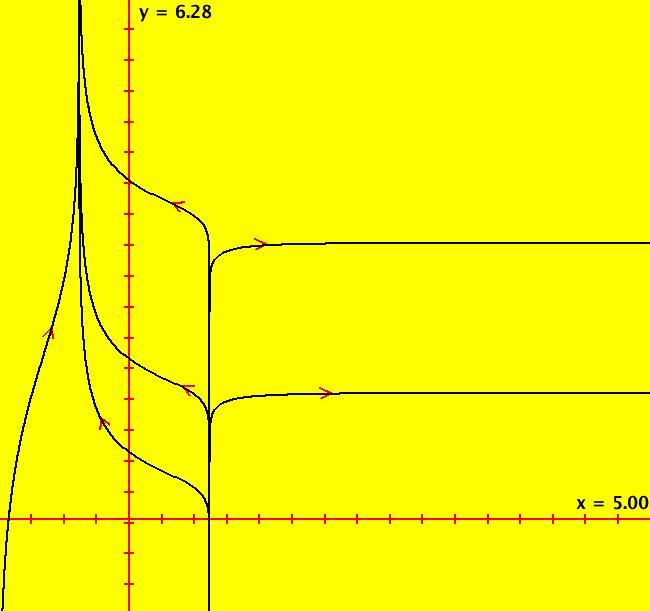
View/Sys/Gal: Ode "2D: p. 247 two limit cycles polar form" in "PerkoExs."
Range: (vMax,vMin) = (6.283,-0.100), (hMin,hMax) = (0.000,5.000)
VFld: ((cos(y)*(-(x*sin(y))+(x*cos(y))*(((x*cos(y))^2+(x*sin(y))^2)^2-3*((x*cos(y))^2+(x*sin(y))^2)+1))+sin(y)*((x*cos(y))+(x*sin(y))*(((x*cos(y))^2+(x*sin(y))^2)^2-3*((x*cos(y))^2+(x*sin(y))^2)+1))),(cos(y)*((x*cos(y))+(x*sin(y))*(((x*cos(y))^2+(x*sin(y))^2)^2-3*((x*cos(y))^2+(x*sin(y))^2)+1))-sin(y)*(-(x*sin(y))+(x*cos(y))*(((x*cos(y))^2+(x*sin(y))^2)^2-3*((x*cos(y))^2+(x*sin(y))^2)+1)))/x) This system of odes is defined by the equations: dx/dt = (cos(y)*(-(x*sin(y))+(x*cos(y))*(((x*cos(y))^2+(x*sin(y))^2)^2-3*((x*cos(y))^2+(x*sin(y))^2)+1))+sin(y)*((x*cos(y))+(x*sin(y))*(((x*cos(y))^2+(x*sin(y))^2)^2-3*((x*cos(y))^2+(x*sin(y))^2)+1))), dy/dt = (cos(y)*((x*cos(y))+(x*sin(y))*(((x*cos(y))^2+(x*sin(y))^2)^2-3*((x*cos(y))^2+(x*sin(y))^2)+1))-sin(y)*(-(x*sin(y))+(x*cos(y))*(((x*cos(y))^2+(x*sin(y))^2)^2-3*((x*cos(y))^2+(x*sin(y))^2)+1)))/x.
|
|
|
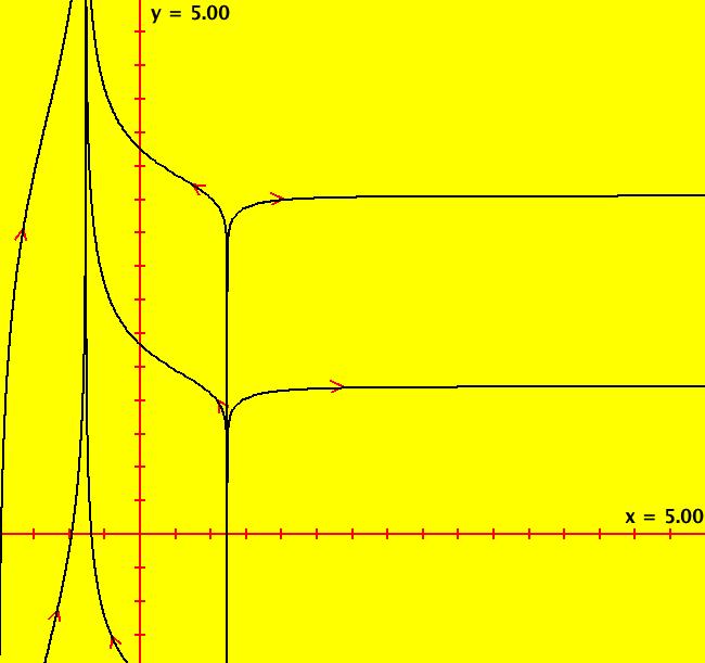
View/Sys/Gal: Ode "2D: p. 247 two limit cycles polar form simplified" in "PerkoExs."
Range: (vMax,vMin) = (5.000,0.000), (hMin,hMax) = (0.000,5.000)
VFld: (x^5-3*x^3+x,1) This system of odes is defined by the equations: dx/dt = x^5-3*x^3+x, dy/dt = 1. correct form from dr/dt = cos( θ)*dx/dt+sin( θ)*dy/dt, d θ/dt = (cos( θ)/r)*dy/dt-(sin( θ)/r)*dx/dt looks like rect -> polar code is not quite correct
|
|
|
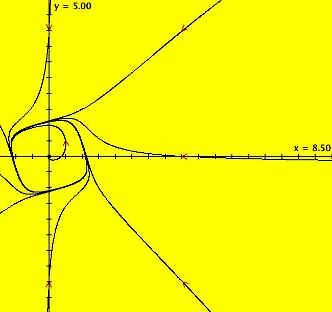
View/Sys/Gal: Ode "2D: p. 249 (x-y-x^3,x+y-y^3)" in "PerkoExs."
Range: (vMax,vMin) = (5.000,-5.000), (hMin,hMax) = (-1.500,8.500)
VFld: (x-y-x^3,x+y-y^3) This system of odes is defined by the equations: dx/dt = x-y-x^3, dy/dt = x+y-y^3 The finite fixed point is (x,y) = (0,0). Let P3 = -x^3 and Q3 = -y^3, that is, the terms of degree 3 on the on the right hand sides of the system. The fixed points at infinity satisfy v*P3(u,v) = u*Q3(u,v), u^2+v^2 = 1. (Perko, Theorem 1, p. 268) In the 3D/(t,x,y) view, we see that the period of the limit cycle is about 7.
|
|
|
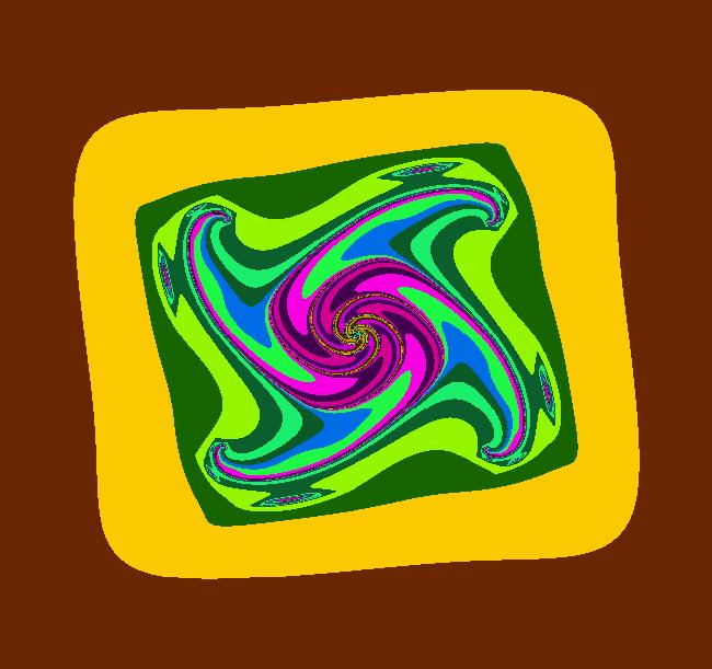
View/Sys/Gal: EMap "2D: p. 249 (x-y-x^3,x+y-y^3) EMapCT5" in "PerkoExs."
Range: (vMax,vMin) = (2.941,-2.958), (hMin,hMax) = (-2.704,2.704)
VFld: (x-y-x^3,x+y-y^3) This iteration is defined by: x <- x-y-x^3, y <- x+y-y^3. EMap CT: 5
|
|
|
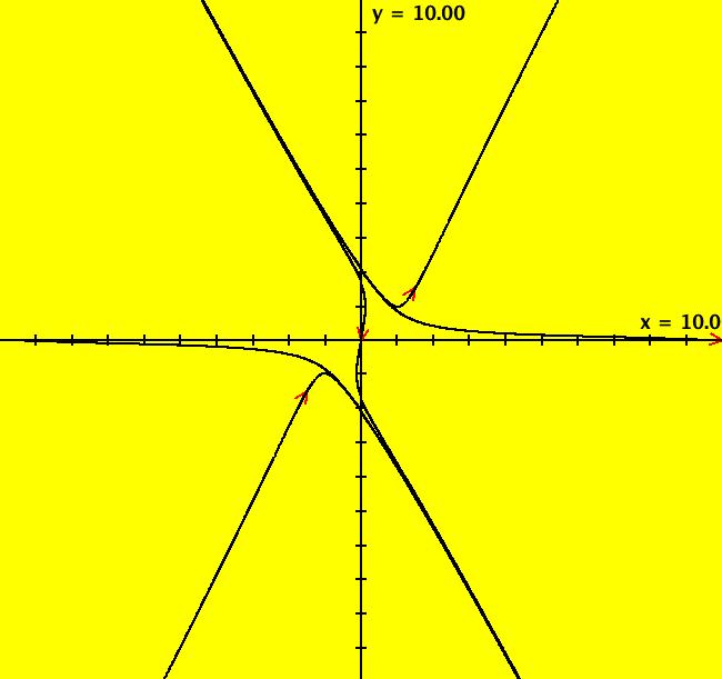
View/Sys/Gal: Ode "2D: p. 272 (x^2+y^2-1,5*(x*y-1))" in "PerkoExs."
Range: (vMax,vMin) = (10.000,-10.000), (hMin,hMax) = (-10.000,10.000)
VFld: (x^2+y^2-1,5*(x*y-1)) This system of odes is defined by the equations: dx/dt = x^2+y^2-1 = P(x,y), dy/dt = 5*(x*y-1) = Q(x,y) There are no finite fixed points. The critical points at infinity satisfy: u*P2(u,v) = v*Q2(u,v), z = 0 or u*(5*u*v) = v*(u^2+v^2), u^2+v^2 = 1 WA gives the 6 solutions: +-(1,0), +-(1,2)/sqrt(5) and +-(1,-2)/sqrt(5). The approximate separatrices for the system are given by the two trajectories with ICs (x,y) = (+-10,0) which give Perko's global phase portrait figure 7 on p. 274 in the R2+ view. Perko's equation (7), p. 269 gives the flow at infinity as: -dy/dt = y*z^2*P(1/z,y/z) - z^2*Q(1/z,y/z) -dz/dt = z^3*P(1/z,y/z). Note that all terms of P and Q are used, not just the highest order terms. So for our system, dy/dt = 4*y-5*z^2-y^3+y*z^2, dz/dt = -z-z*y^2+z^3 which are Perko's equations (8), p. 273. This 2D system can be studied in OdeFactory as a 3D system by adding the equation dx/dt = 0 and using the (y,z) view with x(0) = 0. See system "3D: p. 273..." in this gallery. This system has fixed points at (y,z) = (0,0), (+-2,0). See the next system for an analysis of the flow at infinity using the dy/dt, dz/dt equations in OdeFactory.
|
|
|
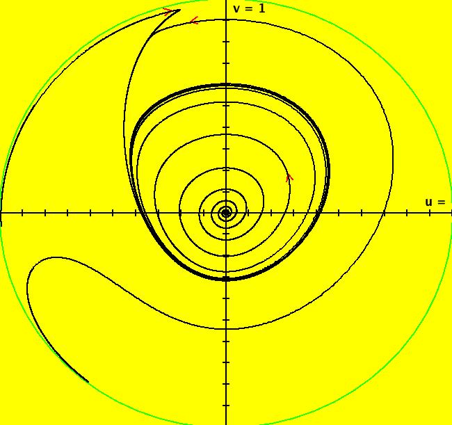
View/Sys/Gal: Ode "2D: p. 276 (-y*(1+x)+a*x+(a+1)*x^2,x*(1+x)), a=.2" in "PerkoExs."
Range: (vMax,vMin) = (1.000,-1.000), (hMin,hMax) = (-1.000,1.000)
VFld: (-y*(1+x)+a*x+(a+1)*x^2,x*(1+x)), a=.2 This system of odes is defined by the equations: dx/dt = -y*(1+x)+a*x+(a+1)*x^2, dy/dt = x*(1+x) Parameters are: a=.2 where 0 < a < 1. Perko, p. 276, fig 9. There is a finite fixed point at (x,y) = (0,0) and there is a limit cycle about the fixed point. To see the limit cycle get into the R2 view, clear the view and start a flow animation with 5 dots and max speed. Click the "Start Flow" button to add dots while the animation runs. To find the fixed points at infinity, use WA on sin( θ)*(-cos( θ)*sin( θ)+1.2*cos( θ)^2) = cos( θ)*cos( θ)^2 to get θ ~= +- pi/2. So the fixed points at infinity are at (u,v) ~= (0,+-1). The R2+ view shows the global phase portrait.
|
|
|
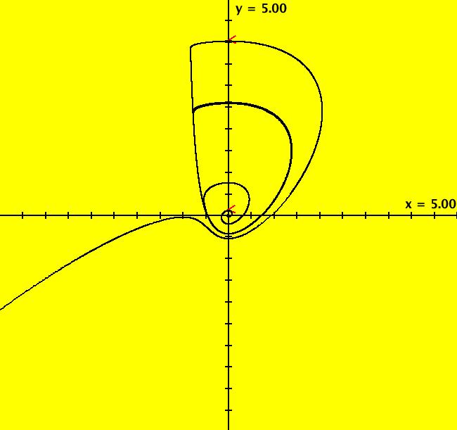
View/Sys/Gal: Ode "2D: p. 292 (a*x-y+(a+1)*x^2-x*y,x+x^2), a=.5" in "PerkoExs."
Range: (vMax,vMin) = (5.000,-5.000), (hMin,hMax) = (-5.000,5.000)
VFld: (a*x-y+(a+1)*x^2-x*y,x+x^2), a=.5 This system of odes is defined by the equations: dx/dt = a*x-y+(a+1)*x^2-x*y, dy/dt = x+x^2 Parameters are: a=.5 For -1 < a <= 0 (0,0) is a spiral sink and for 0 < a < 1 there is a limit cycle about (0,0). The limit cycle is a separatrix. The bifurcation value is a = 0.
|
|
|
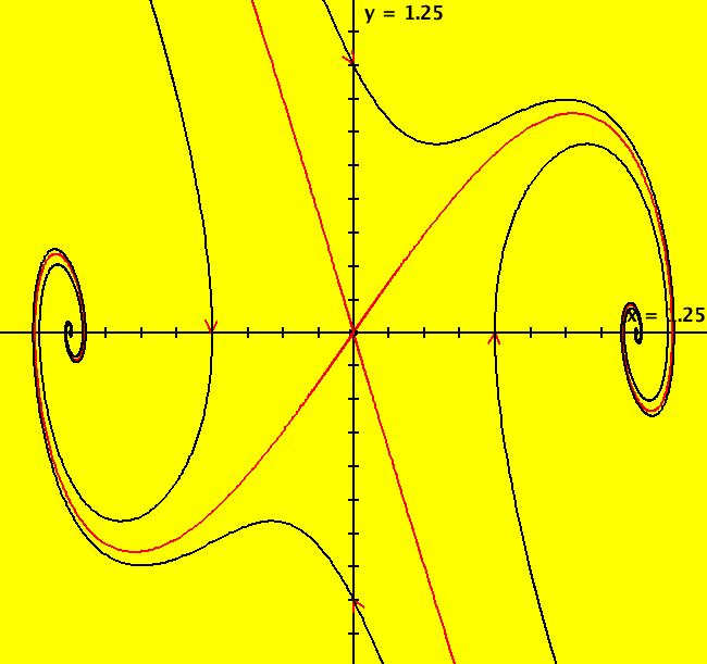
View/Sys/Gal: Ode "2D: p. 320 (y,a*y+b*x*(1-x^2)), a = -1.10; b=1 ver 2" in "PerkoExs."
Range: (vMax,vMin) = (1.250,-1.250), (hMin,hMax) = (-1.250,1.250)
VFld: (y,a*y+b*x*(1-x^2)), a = -2.00; b = 5.30; This system of odes is defined by the equations: dx/dt = y, dy/dt = a*y+b*x*(1-x^2) in the (t,x,y) coordinate system. The 1st order 2D system corresponds to the 2nd order ode y'' = a*y'+b*y*(1-y^2) in the (x,y,y') coordinate system. Parameters are: a = -2.00; b = 5.30; Try the EMap view.
|
|
|
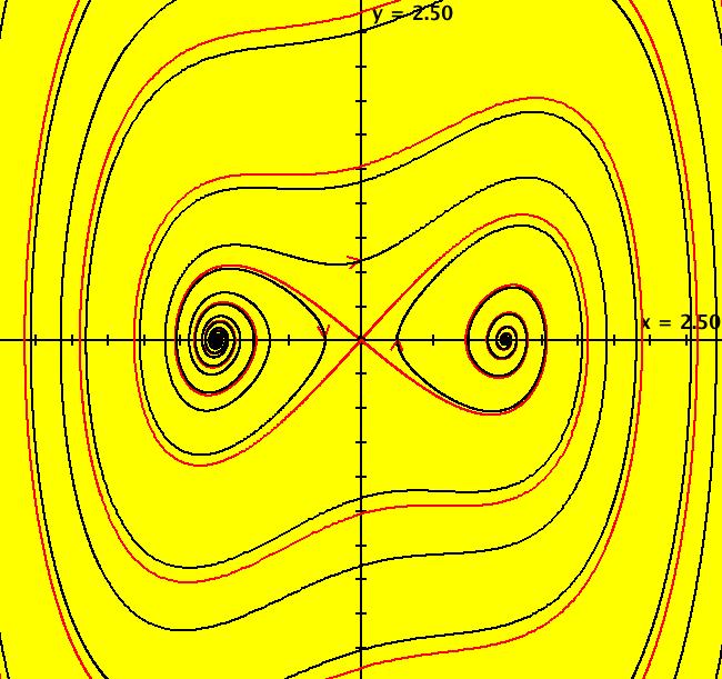
View/Sys/Gal: Ode "2D: p. 320 (y,a*y+x*(1-x^2)), a = .30; " in "PerkoExs."
Range: (vMax,vMin) = (2.500,-2.500), (hMin,hMax) = (-2.500,2.500)
VFld: (y,a*y+x*(1-x^2)), a = .30; This system of odes is defined by the equations: dx/dt = y, dy/dt = a*y+x*(1-x^2) in the (t,x,y) coordinate system. Parameters are: a = .30; ICs at (0,0) are: (0,+-.001). There are separatrices for all "a" but there is only a separatrix cycle for a = 0. The same is true for the damped pendulum. Adjust parameter "a" to see what happens near a = 0. Try both the R2 and R2+ views.
|
|
|
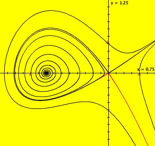
View/Sys/Gal: Ode "2D: p. 392 (y,x+x^2-x*y+a*y), a = -.864; " in "PerkoExs."
Range: (vMax,vMin) = (1.250,-1.250), (hMin,hMax) = (-1.750,0.750)
VFld: (y,x+x^2-x*y+a*y), a = -.864; This system of odes is defined by the equations: dx/dt = y, dy/dt = x+x^2-x*y+a*y in the (t,x,y) coordinate system. Parameters are: a = -.864; The finite fixed points are at (0,0) and (-1,0). This is a difficult system to draw a separatrix for. The IC for the approximate separatrix is (0,-.001). Other ICs are: (0,.5), (.5,0) and (-1.25,0). Delete the trajectory starting at (-1.25,0) for a better view of the approximate separatrix. Pan right until the fixed point is centered in the view then zoom in until you to see the error in the approximate separatrix. Adjust "a" to see what happens. Try the EMap view with a = +-.04, -.27.
|
|
|
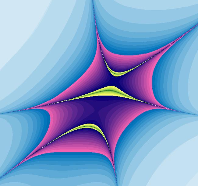
View/Sys/Gal: EMap "2D: p. 392 (y,x+x^2-x*y+a*y), a = -.864; EMapCT3" in "PerkoExs."
Range: (vMax,vMin) = (0.636,-2.212), (hMin,hMax) = (-2.306,0.306)
VFld: (y,x+x^2-x*y+a*y), a = -.350; This iteration is defined by: x <- y, y <- x+x^2-x*y+a*y. Parameters are: a = -.350; EMap CT: 3
|
|
|
View/Sys/Gal: Ode "3D: p. 53 (-y,x,z/5)" in "PerkoExs."
Range: (vMax,vMin) = (5.000,-5.000), (hMin,hMax) = (-5.000,5.000)
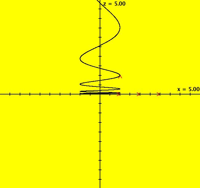
VFld: (-y,x,z/5) This system of odes is defined by the equations: dx/dt = -y, dy/dt = x, dz/dt = z/5 This is Perko's fig. 2, p. 53. The fixed point is at the origin. The center manifold, Ec, is the (x,y) plane. The unstable manifold, Eu, is the z axis. R3 = Eu ⨁ Ec ICs are: (1,0,1), a spiral about the z axis (x,0,0) for x = 1, 2, 3 which are circles in the (x,y,0) plane See the 3D/(x,y,z) view.
|
|
|
View/Sys/Gal: Ode "3D: p. 105 (-x,-y+a*x^2,z+a*x^2), a=0" in "PerkoExs."
Range: (vMax,vMin) = (5.000,-5.000), (hMin,hMax) = (-5.000,5.000)
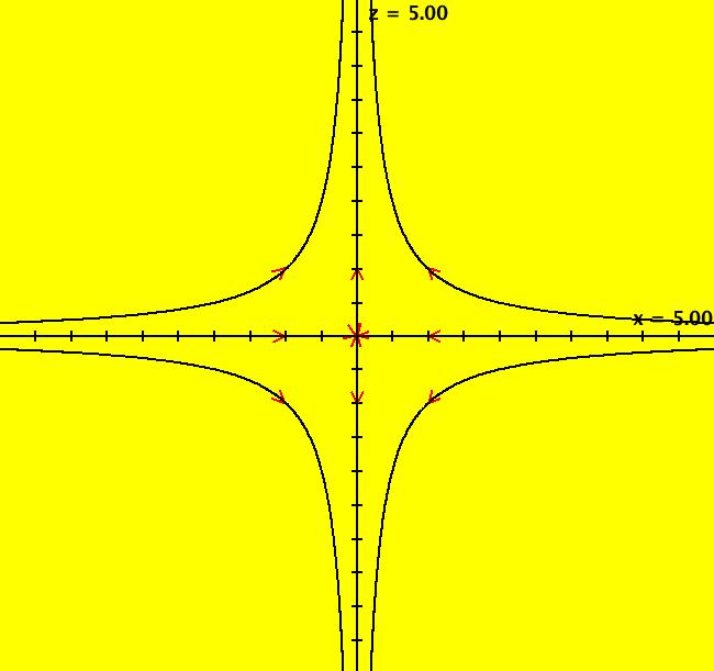
VFld: (-x,-y+a*x^2,z+a*x^2), a=0 This system of odes is defined by the equations: dx/dt = -x, dy/dt = -y+a*x^2, dz/dt = z+a*x^2 Parameters are: a=0 The linearized system is the a = 0 system for which: fixed points (x,y) = (0,0) and at inf, (u,v) = (+-1,0), (0,+-1) eigenvalues λ1 = -1, λ2 = 1 eigenvectors (1,0) and (0,1) separatrix ICs: (+-.001,0), (0,+-.001) stable manifold Es = x axis (separatrices: y = 0, x > 0 and x < 0) unstable manifold Eu = y axis (separatrices: x = 0, y > 0 and y < 0) center manifold Ec = null note: R2 = Es ⨁ Eu ⨁ Ec other ICs: (+-1,+-1), (+-1,0), (0,+-1) For a = 1 the stable manifold is the surface z = -x^2/3, and the unstable manifold is the z axis. The (x,z) view is in the (x,0,z) plane. Watch what happens as a -> 1 and as a -> -1.
|
|
|
View/Sys/Gal: Ode "3D: p. 105 (-x,-y+x^2,z+x^2)" in "PerkoExs."
Range: (vMax,vMin) = (5.000,-5.000), (hMin,hMax) = (-5.000,5.000)
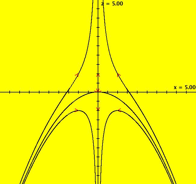
VFld: (-x,-y+x^2,z+x^2) This system of odes is defined by the equations: dx/dt = -x, dy/dt = -y+x^2, dz/dt = z+x^2 Stable manifold is the surface z = -x^2/3. Unstable manifold is the z axis. The view is in the (x,0,z) plane. The y axis is into the screen.
|
|
|
View/Sys/Gal: Ode "3D: p. 273 (0,4*y-5*z^2-y^3+y*z^2,-z-z*y^2+z^3)" in "PerkoExs."
Range: (vMax,vMin) = (4.000,-4.000), (hMin,hMax) = (-4.000,4.000)
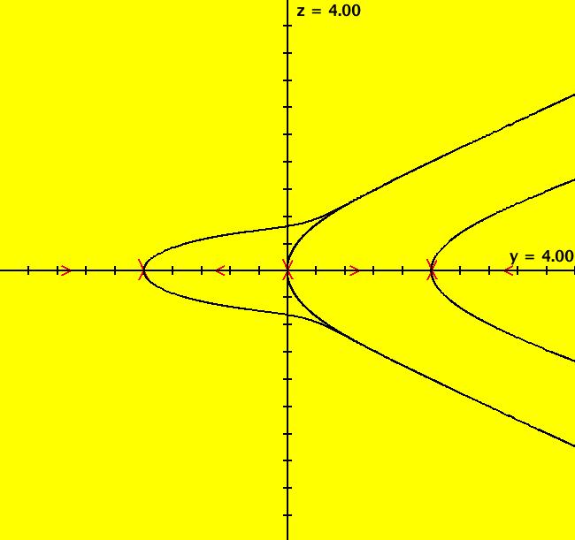
VFld: (0,4*y-5*z^2-y^3+y*z^2,-z-z*y^2+z^3) This 3D system of odes is defined by the equations: dx/dt = 0, dy/dt = 4*y-5*z^2-y^3+y*z^2, dz/dt = -z-z*y^2+z^3 It is the analysis of the dy/dt, dz/dt part of the system that is of interest. The dy/dt, dz/dt system is the projection of 2D flow defined by system "2D: p. 272..." in this gallery dx/dt = x^2+y^2-1, dy/dt = 5*(x*y-1) onto the top half of the Poincare unit sphere in R3 and then onto a plane tangent to the unit sphere perpendicular to the y axis. The dy/dt, dz/dt equations of the 3D system are used to study the "flow of the 2D system at infinity." The 3D quations come from Perko's equation (7), p. 269: -dy/dt = y*z^2*P(1/z,y/z)- z^2*Q(1/z,y/z), -dz/dt = z^3*P(1/z,y/z). The - sign is used to get the correct direction of the flow at infinity (on the unit circle in the R2+ view). The (y,z) view, with x = 0, gives Perko's, fig. 6, p. 273. Perko's figure has the trajectories at (y,z) = (+-2,0) tangent to the y axis but they should be tangent to the separatrices that are perpendicular to the y axis at y = +-2 as shown in the (y,z) view. You can also check this in OdeFactory by turning on the vector field after rewriting the 3D system as the 2D system dx/dt = 4*x-5*y^2-x^3+x*y^2, dy/dt = -y-y*x^2+y^3
|


